
An infinity pool plan is not simply an outline of the pool shape. Long before construction begins, the technical documentation must define with precision the overflow edge, the hydraulic scheme, the pipe routing and the organisation of the technical spaces.
This is where many projects are quietly won or lost. At this stage, many of the decisions that will later shape the correct execution and coordination of the works are taken.
A beautiful concept without complete coordinated technical documentation leaves the most important questions unresolved, aspects that, if they are not resolved beforehand, can turn into interferences, changes and cost overruns during execution.
Here we explain what a complete set of infinity pool design plans should cover, and why each document matters.
Why an infinity pool needs complete technical documentation
Although certain pools have simpler hydraulic configurations, any project requires correct technical definition.
In an infinity pool, this coordination becomes even more relevant because of the interaction between the overflow edge, the hydraulics, the balance system and the architecture.
As we explain in our guide to how an infinity pool works, the visual finish of the water surface depends on very precise control of the levels and the levelling of the overflow edge.
A conceptual scheme can serve to communicate the design intent and advance the early phases of the project, but it does not replace the technical documentation needed for its definition and execution.
➜ That technical development resolves the heart of the project: how the edge is built, how the water is collected and returned, and how the equipment is sized.
A complete set of documentation answers all of this before excavation begins.
Each element is interdependent, so a change in one affects the others, and that is why all these elements must be designed in a coordinated way to favour stable hydraulic operation and an execution consistent with the design.
What a complete plan set must include
A well-resolved technical development brings together the architectural, structural and hydraulic information a project needs to execute the works with greater precision and to reduce improvised decisions during construction.
The core documents typically include the following:
| Drawing / document | What it defines |
| Ground plan (plan view) | The pool geometry, dimensions and position on the plot, with the overflow edge located. |
| Sectional drawings | The depth profiles, water levels and the overflow edge detail in cross section. |
| Overflow edge detail | The weir geometry, the collection channel and how the water is collected. |
| Pool hydraulic scheme | Definition of the recirculation, supply, suction, overflow, drain and treatment circuits, and their connection to the plant room. |
| Hydraulic elements and service penetrations plan | Position and levels of nozzles, drains, wall penetrations, lights and other elements to be coordinated with structure and waterproofing before concreting. |
| Balance tank detail | The tank position, volume criteria and level-control connections. |
| Structural and waterproofing coordination | Definition of the junctions between shell, overflow edge, channels, joints and penetrations, coordinated with the structural solution and the waterproofing system. |
| Plant room drawing | The arrangement and coordination of the main equipment and circuits: pumping, filtration, treatment, valve sequence and level control. |
Overflow edge geometry
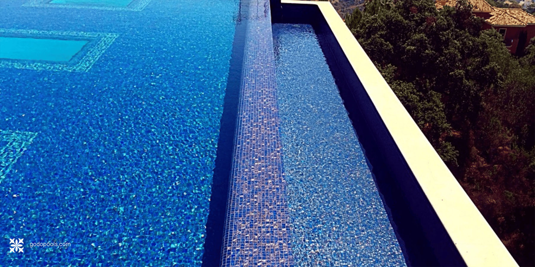
The overflow edge is the element that defines an infinity pool, and one of the elements that demands the greatest precision in the technical development. The weir replaces the coping on one or more sides, allowing the water to spill over.
The plans define the exact level of the edge, its profile and how it meets the surrounding terraces. The visual continuity of the effect depends on precise levelling and a homogeneous distribution of the flow along the edge.
At this stage the most suitable overflow typology is also defined (negative edge, perimeter overflow, hidden channel or other solutions) according to the architecture, the levels, the views and the desired visual effect.
The pipe network and its routing
Beneath the visible pool lies a network of pipes that makes the overflow work. The hydraulic scheme maps this network completely:
-
- Supply and recirculation circuits.
-
- Suction lines and drains.
-
- Overflow and balance lines.
-
- Emptying and drainage.
-
- Connections with treatment and climate control, where applicable.
-
- Routing and connection to the plant room.
Without a detailed hydraulic scheme, it is difficult to position the elements correctly or to size the pumping, filtration, treatment and regulation equipment, and the balance system, according to the specific conditions of the project.
Defining the pipe routing correctly eases execution, reduces interference with other installations and allows the hydraulic conditions of the system to be optimised.
The behaviour of the water will also depend on the sizing of flow rates, the head losses and the distribution of the supply and suction points.
Balance tank sizing
The balance tank absorbs the changes in water volume that an overflow pool produces in use.
The technical documentation locates the tank, defines its connections and sets out the criteria for its volume. We look at this component in detail in our guide to the swimming pool balance tank.
Rather than applying a fixed percentage, the tank should be calculated for each project, considering the geometry and length of the overflow system, the volume in circulation, the anticipated occupancy, the operational needs and, in outdoor installations, rainfall inputs.
The technical documentation records the resulting sizing and its operating conditions.
Plant room and equipment layout
The design of the plant room conditions the operation, accessibility and maintenance of the hydraulic system.
➜ The plant room drawing defines the arrangement and coordination of the main equipment and circuits: the position of the pumps and filters, the pipe connections, the valve sequence, the water treatment and the level control.
The equipment is arranged in a logical sequence that follows the hydraulic circuit, from pool suction through to return, via filtration and treatment.
The layout must also allow for the distances needed for maintenance, access to pumps, filters and treatment equipment, the possibility of replacing components, and the requirements for ventilation, drainage and operational safety.
Well-developed documentation eases coordination between designers, project management and execution teams, but it must be accompanied by professionals with sufficient experience in hydraulic systems and overflow pools.
Why specialist technical development prevents costly errors
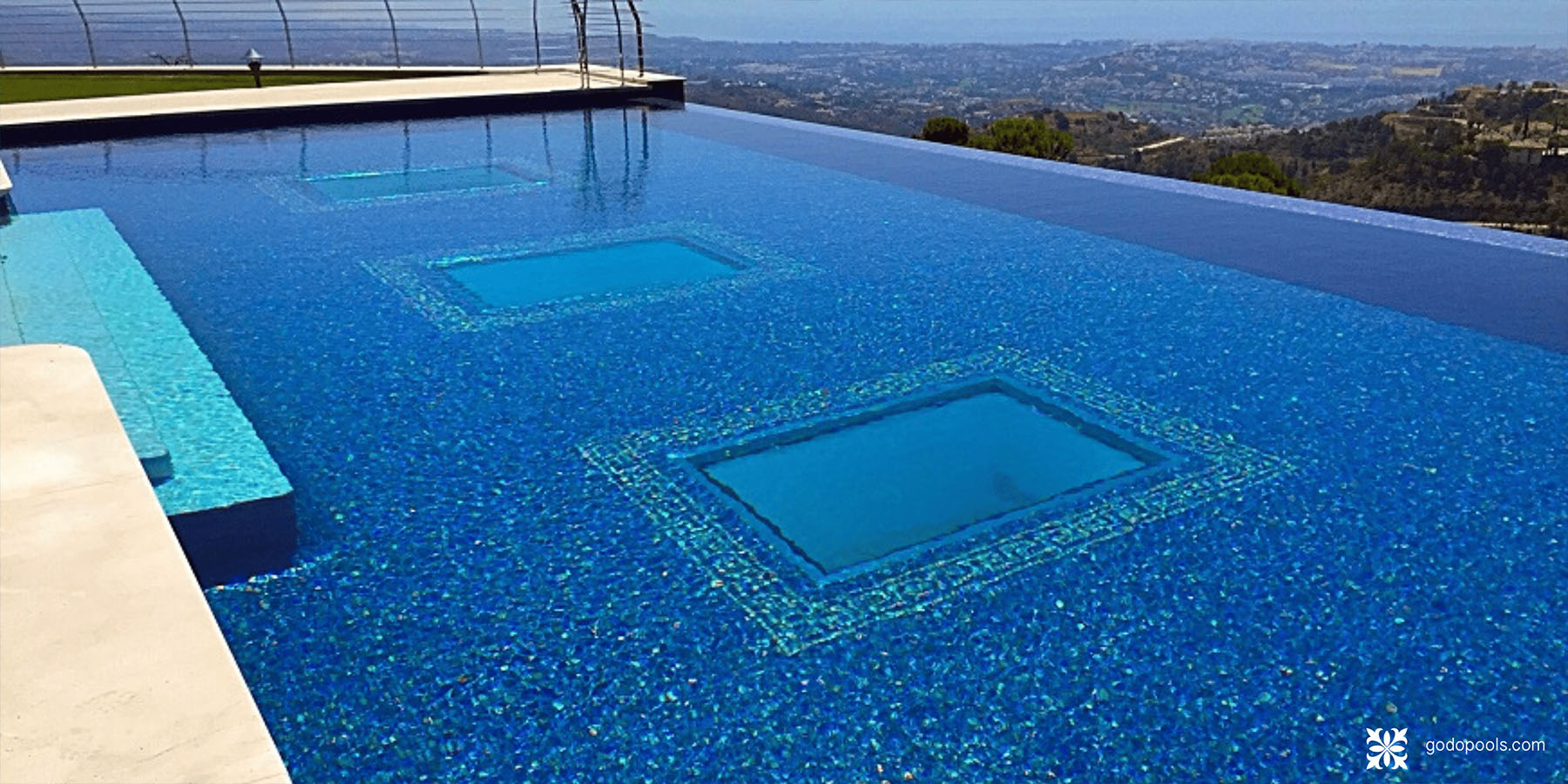
Infinity pools require particularly rigorous control of levels and execution tolerances, beyond that of a conventional pool.
Small deviations in the levelling of the edge can produce an uneven distribution of the water and compromise the visual continuity of the overflow.
Specialist technical development translates the design into coordinated technical information that allows the execution team to understand and correctly build the intended solutions, defining the pool structure, the overflow channel, the balance system and the junctions between structure, waterproofing, hydraulics and finishes that condition the correct execution of the project.
Understood this way, the technical documentation is not paperwork. It is an essential tool to reduce uncertainty, coordinate disciplines and anticipate decisions before execution, coordinating architecture, structure and hydraulics from the earliest project phases to favour a built result that preserves the architectural intent and the technical performance defined in the project.
Conclusion
A complete set of technical documentation for an infinity pool is what turns an idea into a project that is technically defined, coordinated and ready for execution.
From the overflow edge to the plant room, complete technical documentation makes it possible to anticipate and resolve many of the decisions that would otherwise be carried over into the construction phase.
At GodoPools we develop and validate Architecture of Water solutions from an architectural, hydraulic and constructive perspective, producing the technical documentation needed to take each concept to site rigorously.
If you are developing an overflow pool or a complex Architecture of Water project, our team can help you review the concept, define the hydraulic engineering and develop the technical documentation needed from the earliest phases. Contact us here.

Frequently asked questions (FAQ)
➜ What does a complete set of infinity pool plans include?
Typically a ground plan with the pool geometry, sectional drawings, the overflow edge detail, the hydraulic scheme, the hydraulic elements and service penetrations plan, the structural and waterproofing coordination, the balance tank detail and the plant room drawing. Each element is interdependent and developed in a coordinated way.
➜ Can an architect develop the hydraulic scheme for an infinity pool?
An architect usually defines the concept and its relationship with the building, but the hydraulic development of an overflow pool requires specific technical expertise and coordination with structure and waterproofing, so it is generally developed by a specialist.
➜ Why is the documentation for an infinity pool more demanding than for a standard pool?
Because the continuity of the effect depends on precise levelling and a homogeneous distribution of the flow along the overflow edge. That is why the documentation must define the levels, the junctions and the hydraulics with particularly rigorous control.
➜ How is the balance tank size shown in the documentation?
The documentation locates the tank and defines its connections and level control. Its volume should be calculated specifically for each project, rather than set by a fixed rule, and the documentation records the resulting sizing and its operating conditions.